


A successful construction project relies on a collection of detailed plans, and among the most critical are the electrical drawings. These documents are the comprehensive roadmap for a building’s entire electrical system, detailing everything from where outlets will be placed to how the main power supply connects to every circuit. Without a clear and accurate electrical plan, a project risks delays, budget overruns, and significant safety hazards.
This guide will explain what electrical drawing services are and why they are an indispensable part of any construction project. We will cover the different types of drawings you’ll encounter, how to interpret them, and the role modern technology plays in their creation. Understanding these documents is fundamental for ensuring a project is completed safely, on budget, and in full compliance with all regulations.
Why Electrical Drawings Are So Important
Electrical drawings are much more than just lines on paper; they are the backbone of a building’s electrical infrastructure. Their importance can be broken down into three key areas: accuracy, safety, and compliance.
Ensuring Accuracy and Efficiency
A detailed electrical drawing provides a clear visual representation of the entire electrical system before any physical work begins. This allows architects, engineers, and electricians to identify potential issues, optimize the layout, and coordinate with other trades, like plumbing and HVAC. By resolving conflicts during the planning phase, projects can avoid costly and time-consuming rework later on.
These plans ensure every component is accounted for, from the main switchboard to the smallest light switch. This precision helps in ordering the correct quantity of materials, reducing waste and preventing budget blowouts. For project managers, these drawings serve as a vital tool for scheduling tasks and ensuring the construction process flows smoothly.
Promoting Safety
Electricity is inherently dangerous, and improper installation is a leading cause of construction site accidents and future fire hazards. Electrical drawings are a critical safety tool that outlines safe installation practices. They specify the correct wire sizes, circuit breaker ratings, and grounding methods needed to prevent overloads, short circuits, and electrical shocks.
During construction, electricians rely on these drawings to install the system correctly. After the building is complete, the drawings remain an essential reference for maintenance, troubleshooting, and future renovations. A clear record of the electrical system helps technicians safely identify and isolate circuits when performing repairs, protecting both the workers and the building’s occupants.
Meeting Regulatory Compliance
Building codes and electrical standards, such as the National Electrical Code (NEC) in the United States, are legally enforceable regulations designed to ensure safety and functionality. Electrical drawings are required to demonstrate that a project’s design complies with these complex codes.
Before construction can even start, these plans must be submitted to local authorities for approval. A thorough and compliant drawing, often created by professional electrical drawing services, streamlines the permitting process. Without approved drawings, projects can face significant delays and legal penalties. They serve as documented proof that the electrical system has been designed and installed to meet all required safety standards.
Common Types of Electrical Drawings
Electrical systems are complex, and different types of drawings are used to represent various levels of detail. Understanding the purpose of each type is key to managing a construction project effectively.
Single-Line Diagrams (SLDs)
A single-line diagram is a high-level overview of an electrical system. As the name suggests, it uses a single line to represent the power flow between major components like transformers, switchgear, and panelboards. SLDs are not concerned with the physical layout but focus on the system’s logic and function. They are essential for understanding power distribution and performing load calculations.
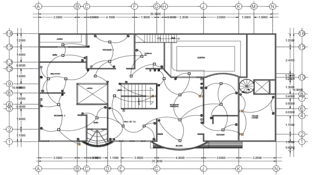
Wiring Layouts
Wiring layouts show the physical location of all electrical components, including lights, switches, outlets, and appliances. These drawings are overlaid on the building’s floor plan to provide a real-world context. They detail the paths that wires will take through walls, floors, and ceilings, guiding the electricians during the installation phase.
Schematic Diagrams
Schematic diagrams provide a more detailed look at the connections within a circuit. Unlike wiring layouts, schematics are not drawn to scale. Instead, they use standardized symbols to represent components and show how they are connected logically. These diagrams are crucial for troubleshooting and understanding how a particular circuit operates.
Panel Schedules
A panel schedule is a table that provides detailed information about a specific electrical panel. It lists every circuit connected to the panel, specifying the circuit number, the load it serves (e.g., “Kitchen Lighting”), the required voltage, and the amperage of the circuit breaker. Panel schedules are vital for balancing loads across the panel and for future maintenance.
How to Read and Interpret Electrical Drawings
Reading electrical drawings requires familiarity with a standardized set of symbols and notations. While it can seem daunting at first, a basic understanding of these elements can make the process much clearer.
Understanding Symbols
Every component in an electrical system is represented by a specific symbol. For example, a circle with an “X” inside might represent a ceiling light fixture, while a circle with two parallel lines represents a duplex receptacle (a standard outlet). Most drawing sets include a legend or symbol key that defines what each symbol means. Taking the time to study this legend is the first step to accurately interpreting the plans.
Following the Lines
The lines on an electrical drawing represent the wires that connect the components. Different types of lines are used to convey different information. For instance, a solid line might indicate wiring concealed in a wall, while a dashed line could represent wiring in the ceiling. The number of slash marks through a line often indicates the number of conductors in that run.
Checking the Notes and Specifications
Drawings are almost always accompanied by notes and specifications that provide additional detail. These notes might specify the type of wire to be used, the mounting height for outlets, or other important instructions that aren’t conveyed by symbols alone. Always read these notes carefully, as they contain critical information for a compliant installation.
The Role of Technology in Electrical Drawings
The days of drafting electrical plans by hand are largely over. Today, Computer-Aided Design (CAD) software has revolutionized the industry, offering speed, precision, and powerful collaborative features.
CAD drafting software, such as AutoCAD or Revit, allows engineers to create highly detailed and accurate 2D and 3D models of electrical systems. These tools make it easy to revise plans, automatically update related documents, and share information seamlessly with the entire project team.
Building Information Modeling (BIM), a more advanced form of CAD drafting, creates an intelligent 3D model of the entire building. This allows for clash detection, which automatically identifies where the electrical system might interfere with other systems like plumbing or structural elements. By catching these issues in the digital model, teams can resolve them before they cause expensive problems on-site. Technology has transformed electrical drawing services from a simple drafting task into a sophisticated engineering process.
The Blueprint for a Successful Project
Electrical drawings are the definitive guide for a building’s electrical system. They provide the accuracy needed for efficient construction, the safety protocols required to protect workers and occupants, and the documentation necessary for regulatory compliance. From high-level single-line diagrams to detailed panel schedules, each drawing plays a vital role in bringing a project to life.
For anyone involved in a construction project, understanding the importance of these documents is non-negotiable. By investing in professional electrical drawing services and leveraging modern CAD Drafting technology, you ensure that your project is built on a foundation of safety, quality, and precision.


